NETHERLANDS: Gear-driven drawworks are safer, weigh less
April 2001 Vol. 222 No. 4 Feature Article THE NETHERLANDS: Gear-driven drawworks are safer, weigh less Gear-driven drawworks are gaining more importance in
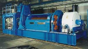
THE NETHERLANDS:Gear-driven drawworks are safer, weigh lessGear-driven drawworks are gaining more importance in the industry. In fact, this innovation has been used almost exclusively in the North Sea during the last few years. Its primary benefits are enormous weight reductions and considerably increased availability, as well as improved safety. With the combined use of dynamic braking and regenerative braking using the drive motors, plus the integration of an intelligent anti-collision system (ACS), a significantly higher safety standard has been realized. The prerequisite for applying this combination was the developmentment by Germany’s Wirth GMBH of a gear-driven drawworks (Fig. 1) with a positive-locking drive configuration and the adaptation of some required features that could not be accomplished to the optimum with chain-driven drawworks. The four-quadrant (4Q) drive required for regenerative braking, for example, represented an almost impossible obstacle for a chain drive.
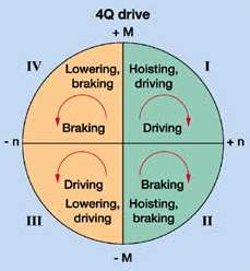
With a 4Q-drive (Fig. 2), energy is processed during all four drive variations of a roundtrip. The first quadrant is represented by breaking-out the drill pipe, where the maximum required energy is used for acceleration during lifting procedures. In this quadrant there is no difference from previous drive configurations.
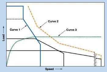
In the second quadrant (lifting operation), braking is achieved by the drive motor by energy feedback prior to reaching the final position. A mechanical brake, which would have been applied in earlier drive configurations is no longer required. In the third quadrant (acceleration on lowering), the acceleration is active, in contrast to the previous application in which the mass inertia moments of the drawworks drum and of the rope sheaves had to be overcome by the gravity of the empty block. The drive motors accelerate as long as the drawworks rope is subject to tensile stress. Thus, a considerable saving of time is achieved. Two offset boreholes showed that a 2,000 hp gear-driven drawworks was negligibly faster accomplishing a 5,000-ft roundtrip than a 3,000-hp chain-driven drawworks. This proved that the physical advantage of 1,000 hp more in lifting capacity was not only eliminated by the Q drive configuration of the gear-driven drawworks; it had also been surpassed. Both drawworks had comparable tensile strengths. With its three-speed design, the gear-driven drawworks was optimally designed for handling casing, the drillstring and operation with low loads, such as an empty block. In the fourth quadrant (braking on lowering), the combination of dynamic braking and regenerative braking with drive motors is always applied in the optimum range required by the system. Here again, a mechanical brake is not required, and the up-to-130 dBA of brake noise is completely eliminated. This represents an improvement in safety and ensures adherence to 85 dBA noise levels in the drillfloor area. The mechanical brake is used only as a parking or emergency brake. Thus, downtime for brake maintenance is almost eliminated. The fluid transition from Quadrants 1 to 2 and/or from 3 to 4 makes high demands on the drive-string components. Gear-wheel drives here show their evident advantages. One can readily imagine the chain slack occurring during the lower lay of drive activity, which promptly changes again into slack during the upper lay of braking activity, and which represents a safety problem. Additionally, the drillstring is subjected to difficult-to-control movements produced as slack changes between lower lay and upper lay conditions. The 4Q-Drive may be used with both DC and AC motors. AC motors have the additional advantage of retaining almost unlimited loads at zero speed, whereas DC motors require a parking brake to take the load after 5 sec to avoid blowing the accumulators. An additional advantage is the slightly higher braking capacity of an AC motor. Optimized Braking System Combination Normally, drawworks DC motors are not used to brake the hook load. The DC motors are disengaged from the drawworks and are slowed to cathead speed by using either regenerative or dynamic braking (energy dissipated within a resistor bank). The new generation of gear-driven drawworks is equipped with two or three main DC or AC motors, which enable the operator to smoothly retard and stop a descending or ascending load without exceeding equipment operating limits. Both DC and AC motors utilize regenerative braking techniques, thereby feeding the braking energy back into the respective 690V/400V or AC chopper resistor bank system. Thus, for an AC drive, a dynamic brake (electro-magnetic or hydraulic) is no longer required. In principle, the above statement is correct, but it should be considered that it reduces working safety and the number of possible drillpipe stands per hour on roundtrip. Curve 1 of Fig. 3 shows the lifting capacity of a three-speed drawworks (better adaptation). Curve 2, which runs parallel to Curve 1, shows the physically limited braking capacity of the respective AC drive. Curve 3 shows the efficiency course of a dynamic brake. The optimum completion of the dynamic brake with the regenerative brakes is distinctly recognizable.
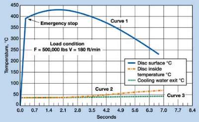
The regenerative brake has its maximum capacity with high loads and low speeds, whereas the dynamic brake performs its maximum with low loads and high speeds. Here, braking capacities up to 6,000 kW are realized. If the dynamic brake is not used, a loss in safety has to be considered in addition to the longer braking time. If, for any reason, the product of load x speed is beyond 1.6 x driving capacity of the electric motors, an accident is almost unavoidable. In this high operating range, the mechanical brake tends to fade, and water cooling does not necessarily improve safety. Casing running operations or comparable work is always executed at reduced speed. In the middle and lower load ranges, in which roundtrips are performed, there is the danger of a dynamic overburden excesses that still must be braked without a dynamic brake. Mechanical brakes have a tendency to fade under such loads, which causes a steadily increasing loss in braking capacity. Tests have proven that, in case of emergency braking without dynamic brakes, temperatures up to 430°C can occur temporarily on the disc when lowering a normal string weight of about 250 tons. One can see the dropping temperature course in the constructional wall thickness of the disc brake, Fig. 4.
Curve 2 of Fig. 4 represents the temperature course in the interior of the disc. The temperature inside only deviates by about 8% from the outside temperature of the brake disc. From this, it is logically concluded that even water cooling does not influence this extreme situation, but is only advantageous on standstill, between make-up and break-out operations during a roundtrip, and then, only if its operation as an active brake is continued despite the extreme noise. Under these conditions, only the combined use of a dynamic brake and a regenerative brake remains practicable for safety reasons. But the same conclusion could be reached for economic reasons as well. With almost equal equipment costs, and the weight of a dynamic brake compared to resistor banks, the loss in operating speed should lead to preferring the dynamic brake. For comparison, a water-cooled resistor bank was used, because otherwise, with an air-cooled unit, further time losses must be taken into account. Both units require almost identical cooling units. The eddy current brake works only on dynamic loads and can neither stop nor hold the static load. This brake is coupled directly to the drawworks shaft in conjunction with the motor brake, depending on the dynamic conditions already described. The dynamic brake, however, is able to brake the load down to zero speed. The drawworks disc brake is equipped with service calipers, which are applied to one braking disc mounted on the drawworks drum. The service calipers consist of three disc pads on each disc. These calipers also are used for the emergency system and are actuated by a spring that applies the braking pads to the discs. These springs are kept open by a hydraulic system, thereby providing a fail-safe system. Any loss of power or hydraulic failure will apply all the calipers. The drawworks control and braking system will only apply the calipers under service conditions for parking, which holds the load in a static condition, thus preventing unintentional lowering or raising of the load. Therefore a cooling system is not necessary. Reduction Of Mass Inertia Moments Braking tests with various drawworks also made evident that, conditioned by the system, higher mass inertia moments have to be taken into account with a gear-driven drawworks. Here, an influence of the mass inertia moments has been ascertained that should not be underestimated. Due to the required form-locking of the 4Q-drivestring, all drive components also have to be considered in the calculation, in addition to the drawworks drum of chain-driven drawworks. Disengaging the drum of a gear-driven drawworks is not possible for safety reasons. For this reason, an optimum weight configuration is the highest priority of the new drawworks. Optimum operating weight and reduction of braking time can only be achieved this way. Compact shifting gears, with a high-reduction ratio, represent the best solution with regard to safety and operation technique at the minimum mass inertia moment possible in spite of their high technical challenge and high price. With the additional drive possibility via an AC drive between 30 and 60 kW, independent of the main drive, a lifting capacity of up to 350 tons at about 215 ft per hr also can be used as redundancy to the main drive, besides the three automatic modes. Therefore, in case of a total AC or DC drive failure, the drillstring can be removed at reduced load. During drilling, automatic operation is possible at constant speed, constant weight and constant mud pressure, which produces a considerable service life for drilling tools, essentially discharges the drilling crew and, with a PC-control, provides an optimum adherence to the given parameters. These advantages can also be realized with the AC technique and the main drive, but since the optimum gearing reduction is not available, the sensitivity and accuracy possible with an autodriller operation is not achieved. Further, the redundancy is lost for handling a failure of the main drive or for positioning components in the mast during start-up of a drilling rig before connecting the main drives. ACS-System The anti-collision system (ACS) is designed to optimize the safety and efficiency of the traveling block’s movement during hoisting and lowering operations. It controls the three individual braking systems of the drawworks. The ACS monitors the drawworks braking systems. Both PLCs calculate independently the position, speed and braking distance required for the hook load. Due to the controlling system algorithm, both PLCs are able to apply the regenerative brake, eddy current brake and disc brake independently, taking into account the system’s kinetic energy and the drawworks braking system’s capacity. Parameters such as hook position, load and required braking distance are checked continuously and compared by both microprocessors, and any discrepancy will be regarded as an ACS fault. The ACS and will activate the DC motor regenerative braking, eddy current brake and the emergency disc brake, to bring the load to a controlled stop. A visual indication and audible alarm for any fault conditions will alert the driller. Both PLCs check the following continuously: Any discrepancy between the two speed and position sensors
All of these faults will be regarded as a total system failure and the DC motor regenerative braking, eddy current brake and disc brake (if required) will be applied. In the automatic mode, the system calculates the optimum braking distance. At a position equal to that of twice the braking distance required, the ACS initiates the DC motor regenerative braking and indicates to the driller that the system is active. At a position that corresponds to the full braking distance required, the eddy current brake also is activated by the ACS. If the system then determines that the DC motors’ regenerative braking efficiency or the eddy current brake is impaired, it will engage the emergency disc brake. In conjunction with the eddy current brake control system, DC motor regenerative braking will be applied to ensure that the maximum eddy current brake rotor speed (drawworks drum speed) is not exceeded. If this speed value is exceeded, eddy current brake efficiency will deteriorate and safety will be compromised. However, the ACS monitors the rotor speed and prevents the drawworks approaching this value by applying the braking system(s). The amount of regenerative braking of the DC motors is dependent upon the connected available power and the "stiffness" of the system. The system takes this into account and calculates the amount of regenerative braking that can be applied. In this case it is limited to 300 kW for each DC drive. The system limits will be set to the maximum upper and lower limits on the ACS terminal located in the driller’s control room. The system provides analysis of the kinetic energy of
the hoisting system, taking into account the braking capacity of the entire system, hook load, speed and
position of the traveling block assembly. |
- Applying ultra-deep LWD resistivity technology successfully in a SAGD operation (May 2019)
- Adoption of wireless intelligent completions advances (May 2019)
- Majors double down as takeaway crunch eases (April 2019)
- What’s new in well logging and formation evaluation (April 2019)
- Qualification of a 20,000-psi subsea BOP: A collaborative approach (February 2019)
- ConocoPhillips’ Greg Leveille sees rapid trajectory of technical advancement continuing (February 2019)

