Innovative construction helps Kakap gas project succeed
RIGS & FACILITIESInnovative construction helps Kakap gas project succeedAs part of Indonesia’s West Natuna project to supply gas to Singapore, Gulf Resources (Kakap) contracted for gas gathering and reception retrofits, plus compression modifications and subsea pipelines. Using innovative construction and contracting practices, this difficult, demanding project was completed in less than 15 months, with no cost overrunsRussell Waugh, Project Manager, Clough Engineering Limited, Jakarta
Not only was KGCP completed significantly ahead of the contract schedule, it was completed in a timeframe that allowed the client to meet objectives beyond the contract’s general realm. At the same time, all process, safety, quality and budget requirements were satisfied fully throughout the design and construction phases. Project Overview Gulf Resources (Kakap) Limited (GRKL) is a production-sharing contractor (PSC) in the West Natuna Transportation System (WNTS JV). In 1999, the WNGP approved contracts for the supply of natural gas to the Singapore market. Each of the PSCs proceeded to embark on plans to meet their supply obligations under the production sharing agreement. For GRKL, this entailed:
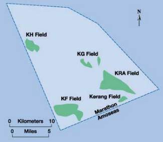
Layout and location of Kakap field are shown in Fig. 1. Existing Kakap facilities were established to extract the field’s oil reserves. Prior to the start of KGCP work, whatever gas was associated with oil production extracted from the wells was either flared or re-injected.
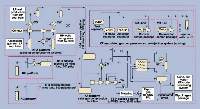
The general KGCP philosophy was to build the necessary facilities to gather, handle and export gas from the field, as an extension to existing oil processing facilities, rather than as a stand-alone operation. At the same time, the project sought to take the opportunity to enhance existing facilities where appropriate, to produce an overall, integrated, oil and gas production facility that is highly efficient and safe. Process Outline A general outline of the process fulfilled by the new facilities is shown in Fig. 2. Gas for export is recovered from wells on KH and KRA platforms. On KH, the wellhead gas is hot and wet. As a result, both cooling and primary liquids knockout are required prior to exporting the gas to KF platform. Because pressures are sufficiently high, supplementary compression is not required. Thus, low-pressure associated gas is flared.
On KRA, gas is currently re-injected. The intent of the new facilities was to modify the existing Solar Centaur-driven, three-stage re-injection compressor to accommodate gas export. Only the part of the process necessary to achieve this would be altered. At the same time, flexibility to re-inject gas whenever not exporting was retained. Some KRA wells flow gas sufficiently at high pressures to avoid export compression – these feed directly to the compressor discharge. The KRA facilities are designed to maximize gas conservation. To this end, the first-stage compressor is set at a level low enough to accept associated gas from the oil production’s low-pressure separator, thus eliminating flaring. On arrival at KF, the KH and KRA gas is passed through separators to remove liquids. The KH gas then enters the first stage of the KF sales gas compressor, before being cooled and combined with gas from KRA at the second-stage compressor’s inlet manifold. From KF oil wells, compressed, associated gas – all of which is currently re-injected – can also be fed to this manifold. From the manifold, the gas passes through dehydration and dew point control before being compressed in the second stage of the sales gas compressor. The gas is then metered, using the latest ultrasonic metering technology, (a first for offshore Indonesia) and exported to Singapore. Dew point control is achieved by passing the process gas through a Joule Thomson (JT) valve, which reduces the pressure and temperature, releasing entrapped liquids. The gas and liquids then separate in the "cold separator vessel." The liquids are sent to the glycol condensate flash drum, downstream. Dehydration of the gas is achieved by injecting tri-ethylene glycol (TEG). TEG is mixed with the gas flow inside the printed circuit-type "gas-gas" exchanger, located before the JT valve. The "gas-gas" exchanger is a highly efficient unit of a type relatively new in the market. As an integral part of the process design, its inclusion allowed significant space savings to be realized, as well as significant process efficiencies. The gas-gas exchanger has three feeds, namely cold gas from the cold separator; cold liquids (rich glycol and condensate) also from the cold separator; and the relatively warm gas being fed to the JT valve. Condensate collected in the inlet separators, suction scrubbers and glycol flash drum is passed into the existing KF oil processing facilities. The efficiency of the dew point control and separation systems designed by the contractor provides substantially better condensate recovery than initially expected by GRKL. Indeed, condensate recovered from the gas processing facilities forms a significant percentage of the overall production at KF platform. Design and Debottlenecking In most projects, the early phases have a profound effect on the overall likelihood of success. Reasons for this may be summarized as follows:
Each of the above points is important, and each, if successfully implemented, enhances the impact and benefits of the others. The quick, decisive start to the engineering development of KGCP, and the rapport developed between client and contractor teams from day one of the contract, enabled the contractor to introduce many design enhancements. One key enhancement involved the gas exchanger (a printed circuit-type exchanger, or PCHE). The contractor optimized the process design by maximizing area, improving heat integration and changing to a three-pass arrangement, (from which flowed reduced glycol circulation requirements and reduced hot oil system duty). This gave rise to significant space savings, while at the same time achieving increased liquid recovery and providing both an improved hydrocarbon dew point and increased sales gas throughput. Understanding GRKL’s overall needs also enabled the contractor to embark on a de-bottlenecking exercise in parallel with the primary, base-case facility design. This allowed the facility to potentially flow an increased throughput of up to 100 MMscfd, compared to the design basis of 66 MMscfd. Because the desire to de-bottleneck and elevate throughput (if possible) was raised and discussed early and openly – and the reasons and relative importance to the client understood – the work did not impact the project schedule, and there was minimal cost to GRKL. Understanding the client’s overall objectives, as regards conservation of gas and contingencies for gas supply, created a flourish of ideas that ultimately developed into design improvements that had benefits for both contractor and operator. The initial design concept did not provide facilities for gas reinjection on KRA and KF once the new compression and export facilities were operating. Working with GRKL, the contractor used its knowledge of the operator’s deeper requirements for operating flexibility to ensure that the ability to re-inject was addressed in the new facilities. Early identification of this criterion increased the contractor’s construction work scope, but it ensured that the extra work was planned and handled without schedule impact. Such changes often are initiated late in a construction cycle and cannot be completed without disrupting the project schedule. Execution GRKL awarded the project execution contract to PT Petrosea on an EPC basis. The contractor’s general execution strategy included:
The contract for the work was awarded on August 6, 1999. Provisional acceptance was granted on October 27, 2000. Complete design, procurement and construction were completed in less than 15 months. Engineering. One of the first key project decisions was to confirm that all topsides design work would be carried out in Jakarta, using a combination of national and expatriate engineers. The Kakap engineering team was established with lead roles in process, instrumentation, structural and rotating equipment filled by Australian expatriate engineers from Perth. These personnel were mobilized to Jakarta for the duration of the engineering work. Indonesian engineers filled all remaining positions. A mixture of nationals and expatriates was also employed in the drafting and design sectors. The decision to carry out engineering and design in Jakarta played an important role in the project’s overall success. First, it minimized the physical constraints limiting client / contractor interaction. Second, it facilitated responsiveness during interaction, which in turn provided a clear understanding of objectives, actions and focus. At each discipline level within the design process, the team worked to seek out improvements and efficiencies. Enhanced process design improved fabrication and installation times by minimizing complexity, and as a retrofit project, where space was at a premium, reducing the demands on real estate. These construction benefits also offered improved maintenance and operation, factors borne out in the start-up process. On the instrumentation and controls side, foundation fieldbus technology was introduced to KF platform, along with new "smart" transmitters wherever possible. This provided a significant, self-diagnostic capability within the field end of the control systems, while at the same time simplifying the cabling installation aspects. The contractor used available state-of-the-art design technology to help eliminate risk areas from the installation phase of the design. This included the use of 3-D PDS modeling of the new facilities, as well as utilization of photogrammetric techniques for verification of the as-built physical condition of existing facilities. Photogrammetry involved taking multiple photographs of the existing facilities, and using advanced graphics software to develop a 3-D electronic image, which could be overlaid with the PDS model. PDS modeling and photogrammetry helped to ensure that the space available offshore was used efficiently, and that clashes were eliminated up front in the design rather than impacting fabrication and installation. The PDS model also made it relatively simple during fabrication and installation for personnel to visualize what had to be installed. With a clear picture, the fabrication and installation teams were better able to focus on their goal. Subsea pipeline design was performed in Perth to take advantage of the necessary specialist engineering services available in Australia. Clough’s Perth-based subsea engineers carried out pipelay installation engineering in-house. The pipelay operation, itself, was not complicated, but the challenge was to develop procedures for such aspects as initialization and riser installation, to achieve maximum efficiency without compromising quality or safety. Thanks to the pipeline engineering team’s ingenuity, the pipelines were installed at record lay rates for the Java Constructor, in the deepest water in which the vessel has laid pipe to date, and ahead of the planned schedule. Installability. A key element of any design, and a designer’s strong asset, is the ability not only to envisage the end product, but the route by which it will get there. The contractor was able to ensure that the design was optimized in all areas for installability. This paid dividends in the overall project execution. The optimization process for installability must evaluate both macro-scale and micro-scale issues. Consider, for example, that a clear objective was to maximize the work that could be done through onshore prefabrication. This led to building as much of the new facilities as possible into skids. Skid designs then had to account for physical size; weight and content; precise location; installation methodology and equipment; associated temporary works; installation route clearances; etc., as macro-scale issues. At the macro level, determining that the three skids to be installed on the production deck would be landed on a temporary deck extension, and skated in along specially designed skid rails, was a key decision that advanced the project along a clear, constructive and optimal path. Refining the optimization process, however, also requires attention to micro issues, such as design of the connection detail between the skid rail and the existing deck structure, and the size and extent of welding required to attach the rail. These are the types of issues that often appear insignificant on paper, but which can make a significant difference to the number of offshore man-days required for fabrication and installation. Fabrication. Onshore fabrication activities were performed in Batam. The choice to fabricate in Batam resulted from:
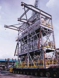
Of special interest were the design, fabrication and installation of the 76-metric ton, 12-m (39-ft) high/10-m (33-ft) long/4-m (13-ft) wide KH knockout skid, Fig. 3. The new KH facilities were, as much as possible, designed into a single skid module, which was to be hung on the side of the existing KH platform via a bucket-and-pin arrangement.
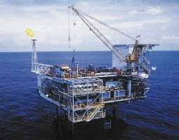
The tall, narrow skid had its primary structural beams at the top level, overhanging the inbound perimeter by about 5 m (16 ft). These overhanging beams incorporated the pins that were to mate with, and lock into, buckets welded to the ends of the existing drill deck’s main, structural beams in three locations. Forming part of the skid at both drill deck and production deck levels, the beams would ultimately be welded to the existing deck beams to form a continuous structure. However, in the installation case, the skid’s full load was to be held in place via the bucket and pin, alone. The key to successful utilization of the bucket-and-pin arrangement had two aspects. First, engineers had to ensure that fabrication was completed sufficiently accurate to the design, to meet tolerances allowable on installation. Second, they had to achieve a bucket design that assisted the installation process, by guiding the deck beams together to achieve the necessary fit-up and welding tolerances, without the need for extensive adjustment offshore. The final design of the tie-in arrangement incorporated guides within the bucket to achieve fit and thickened, bucket connection details (for connection to the existing platform) to maximize the flexibility of the bucket location. This was finally determined after the as-built survey of the skid’s pin locations, to further enhance the chances of a successful offshore fit-up. Following fabrication, the skid was transported approximately 1.6 km (1 mi) to the wharf via public roads, using self-propelled modular transporters (SPMTs), and driven onto the barge. The skid’s sea-fastening was designed to lock the skid in place on the barge, without creating a link between the skid and the sea-fastening that required welding, cutting or other time-consuming means of removal. The fabrication successfully achieved installation tolerances and the skid was lifted, installed and positioned in only about 45 min., Fig. 4. This was a testimonial to the skid’s design and fabrication, and one of the key milestones achieved in the project’s overall completion.
Logistics. Successful execution of the construction phase required the coordination of resources between five key work fronts simultaneously. These were:
Simultaneous operation of these five fronts had numerous advantages for sharing key resources. For example, the Java Constructor was able to install the KH skid while mobilized and set up for riser installation at KH. Key personnel were able to move from one location to another to complete the work rather than remobilize, as would have been true if all activities were sequential. The logistics to achieve these efficiencies were not easy, requiring systems and controls beyond industry norms. Communication was paramount to the logistics process, so the early establishment of viable offshore telecommunications was a key factor. VSAT and HF digital links connected the pipelay barge and platforms to the outside world, and enabled fast, efficient written transmission of data via e-mail and the Internet. This played a key role in successful management of this difficult task. The contractor established and maintained a key materials management system based on in-house "Materials Management System" (MMS) software. Use of this system began at the start of procurement, so that effectively from day one, all materials data were entered and tracked. MMS was supplemented by the use of Excel-based systems for goods receipt and transmission between sites. Excel-based systems also were used for tracking personnel movements. Having the right people at the right place and the right time was a key to ensuring success. Given the many factors that affected movements required on any particular day for optimized work, the resulting planning mechanisms were understandably complex. Some of the relevant factors are outlined below:
Field logistics also were demanding. At peak, the contractor had three vessels in the field providing accommodation for about 350 personnel. These vessels were at different locations, performing varying duties. Inevitably, personnel and materials had to be moved and coordinated between them. A fleet of up to six other vessels / barges also was in the field in support roles, for crew transfer, materials storage, etc. Offshore construction. A principal element in Petrosea’s ability to successfully complete complex construction projects is the ability to draw resources and experience from across the Clough Group. Another key factor is the utilization of design team members at the fabrication and offshore construction sites to provide support to installation crews. This ensures that design information is accurately and efficiently conveyed, and that a history of decisions is carried through, not just the final result contained in the drawings. The offshore construction phase took four months to complete. Work included a variety of tasks, including demolition of redundant existing facilities. A number of installations occurred, including:
There also was an upgrade to existing ESD, F&G and DCS control systems; new insulation; and, of course, painting. New 10-in. and 12-in. subsea pipelines and risers were also installed, as was the 14-in. riser and tie-in spool to the PLEM installed by others adjacent to the KF platform. The effort expended in the design, planning and
fabrication phases ensured that not only did construction progress smoothly, but that the end product was
fully completed and exactly what the client required.
|
|||||||||||||||||||
- Applying ultra-deep LWD resistivity technology successfully in a SAGD operation (May 2019)
- Adoption of wireless intelligent completions advances (May 2019)
- Majors double down as takeaway crunch eases (April 2019)
- What’s new in well logging and formation evaluation (April 2019)
- Qualification of a 20,000-psi subsea BOP: A collaborative approach (February 2019)
- ConocoPhillips’ Greg Leveille sees rapid trajectory of technical advancement continuing (February 2019)

