Smart caliper qualified for measurement-while-drilling operations
A new caliper tool was designed, tested and qualified to overcome fluid density and BHA placement challenges present in MWD calibration, especially during under-reaming operations.
Limitations often exist with ultrasonic caliper measurement technology, due to bottomhole assembly (BHA) placement and changes in fluid density. The concept for a new tool that could effectively handle MWD calibration progressed from design to prototype within three years, following the completion of downhole drilling qualification testing. Outlined below are the R&D methodology, accelerated testing process and successful results of a smart reamer caliper tool that combines on-board proper calibration and multiple sensors, allowing for 360° mapping of the wellbore. Further optional MWD, vibration, magnetic and under-reamer position sensors can be added. The goal in this case was to develop and field-test a prototype for oil and gas drilling, and certified by end-user customers, according to stated criteria. Certification criteria were pressure, temperature, shock, vibration, durability and component life, with minimum on-bottom drilling hours. If proven successfully, the technology and field services, provided by a UK-based drilling technology firm, would be deployed commercially in the field, leading to a new downhole drilling tool system that would save rig operating time and reduce operator well costs. This patented technology consists of a ruggedized printed circuit board (PCB), software, sensors and appropriate steel housings. R&D METHODOLOGYThe R&D methodology adopted a classic stage-gate approach, based on three major stages: Proof of Concept (2007), further research and development (2009), and the verification of the downhole prototype (2011). The final stage, verification, sought to seamlessly integrate all of the lab-tested components of the smart caliper tool into a rugged steel housing and surface decoder, already proven for standard oil and gas drilling. The approach to overcoming this challenge, specifically, included testing of the tool in discrete and incremental stages. With this method, the root cause of any problem was isolated and resolved, before the next test occurred. In this way, the staged tests built confidence and progressively certified the tool for field qualification tests, and, later, for commercial use. The project was supported by Saudi Aramco, and another major operator, and Technology Strategy Board UK. The project was split into four stages and eight work packages, with a view to accelerating the making of a prototype. It was led and managed by Smart Reamer Drilling Systems Ltd., with qualification test requirements provided by Saudi Aramco. A detailed Gantt chart with costs, responsibilities, tasks, durations and contingencies was drawn up and updated, as the project progressed. Extensive customer and supplier input ensured that the development prototype would be fit-for-purpose. Working closely with customers ensured that the technology met field requirements, while a complete testing schedule certified the prototype for commercial use. Working closely with suppliers ensured that each detailed work package would meet field requirements and was manufactured cost-effectively. Tool tests culminated with drilling in several wellbores. It was determined that the tool would be tested to handle:
To transition smoothly from the lab to the downhole environment, each stage concluded with a full reporting of the physical tool condition, real-time data quality, and an emphasis on redesign and rework, as required. The transition included the following stages:
TOOL DEVELOPMENT AND PROJECT MANAGEMENTRisk mitigation is critical to new downhole tool development, and it has been a guiding philosophy for the project. The strategy of the research project has reduced the fundamental risk from a lab point-of-view. Subsequently, each risk type has been assessed, according to its importance, and mitigated systematically, as per the risk table. As a standard method of minimizing risk, modeling and finite element analysis were used to pinpoint critical areas, correcting any design errors before cutting steel and housing sensors. The project was implemented as follows:
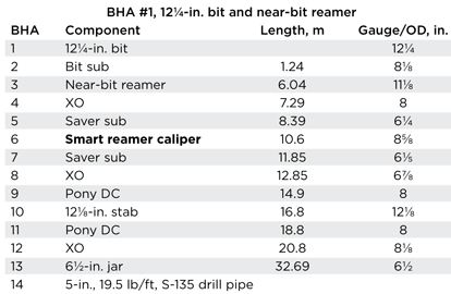
The project team was responsible for verifying the prototype and achieving four key project milestones. The majority of the team was based in the UK, but the project involved four different countries comprising separate companies. Therefore, it was vital to be able to successfully maintain communication and cohesion within the team to achieve the required objectives. The team had already successfully managed the previous conceptual and research project, and was best-placed to transition to the downhole prototype. The continuity of R&D purpose allowed the team to make long-term decisions, while remaining flexible to changing needs, such as re-designing and re-testing. A Gantt chart detailed the 18-month project duration, with the project deliverable concluding as to whether the smart reamer can accurately measure wellbore diameters downhole. Various FEA models were run to enhance the existing design, and involved locating variables and numerical values to determine fatigue, resistance and infinite wear in specific sections, according to standard drilling parameters, such as torque, compression, tension, bending moments, etc. The project team generated a final report with conclusions and de-risks concerning the prototype, so that, before the first commercial test, there would be sufficient confidence in the performance of the smart caliper in a real drilling environment. Customers have provided relevant well data, operational requirements and future field usage. The Smart Caliper project has been geared toward practical field applications and based on actual operating parameters. It is estimated that the operator may save 24 hr of rig time per usage, or more, depending on the application. STATIC TEMPERATURE TESTSThe smart caliper electronics (i.e. operating PCB and wiring) were placed in an industrial Memmert temperature-controlled oven, in compliance with HSE and environmental considerations. Attached to the PCB was a thermocouple, with separate temperature display from the oven, which ensured the correct operating temperature of the PCB was recorded. External connections to the PCB consisted of a transducer immersed in a sample of oil-based mud at 14 lb/g, with a sandstone reflector. The power supply was low-voltage, using a suitable communications interface connected to a computer running smart reamer recording software. An initial calibration test was performed in the laboratory, before equipment was moved to the test facility for the 100-hr test. The equipment was checked and calibrated at an ambient setting, to ensure correct operation. The transducer was placed in the mud at a fixed distance from transducer face to reflector. The temperature was raised continually to 150°C and run for a total of 108 hr, while being cycled off every 12 to 14 hr. The temperature testing was important to ensure that there were no adverse consequences, if electronic components suffered from infant mortality and created functional limitations. Sonic velocities were also observed, as per the temperature cycling and gradient. STATIC PRESSURE TESTSThe smart caliper (i.e. mechanical housing, sensors and other components) was set up for pressure testing in a 15-in. pressure vessel, in compliance with HSE and environmental considerations. A data cable allowed for vessel pressure to be monitored continuously by the data logger, providing an opportunity to identify any pressure breaches. The housing was lifted into the vessel, using an overhead crane, and the pressure was ramped up to 13,053 psi. The pressure was traced via a transducer, and the record was transmitted as an output from the data cable. The testing was conducted initially for 24 hr continuously, and the housing was retrieved and inspected, before continuing the test for a further 75 hr. The pressure test allowed for the direct assessment of all housing components, seals, sensors and mechanical parts. An initial calibration test was performed in the laboratory at slightly-above ambient pressure, before equipment was moved to the test facility for the 100-hr test. The smart caliper housing and components, as well as the pressure vessel, were checked and calibrated at ambient conditions after the test, to ensure correct operation. DRILLING TESTS: WELLS 1 AND 2In the first set of required drilling tests, six runs were conducted, incorporating the smart reamer caliper during field drilling tests in Oxford, UK. The tested tool size was 85/8-in. OD (4½-in. IF connections) in varying BHA sizes, increasing from 97/8 in. to 12¼ in. to 14 in. If it were proven that the smaller tool could take measurements in a large hole, this would add confidence to the overall ability of the caliper to function in larger hole sizes. This would help provide operators with a fit-for-purpose solution that would be an improvement on existing acoustic calipers, both in measurement range and standalone flexible BHA placement. These tests were successful in drilling in 9-in., 12¼-in. and 14-in. hole, in consolidated limestone with highly abrasive flint stringers. Total footage drilled was 100 m, and it provided confidence prior to mobilizing equipment to Norway for further drilling tests. Well 1: Run 1/Run 2/Run 3/Run 4. The formation was a low-lying chalk with quartz inter-bedded brittle shale and quartz. Four runs were performed in hole diameters varying from 97/8 in. to 12¼ in. The BHA runs comprised a pilot hole drilled using a PDC insert bit, both 8½-in. series and 97/8-in. series, with the pilot hole subsequently opened to 12¼ in. by a near-bit reamer, Table 1. The tool was run as a standalone caliper, both with and without modular, full-gauge and under-gauge stabilization in all the pilot and enlarged holes. This provided verification of the pilot and enlarged hole sizes. The smart reamer caliper was also configured with calibration sensors that detected and recorded density changes. The pilot hole BHA was also run slick, while the enlarged hole was run with stabilized BHA, using 12-in. stabilizers, with 65/8-in. REG connections and 10.8 lb/g of water-based polymer mud. Operational parameters, such as surface rotational speed, torque, vibration, pressure, pump rate, flowrate, weight, etc., were recorded, along with the penetration rate.
Well 2: Run 1/Run 2. Two runs were performed in hole diameters varying from 9 in. to 14 in. Drilling comprised a pilot hole using a 97/8-in. series PDC insert bit, with the pilot hole opened subsequently to 12¼ in. by a near-bit hole opener. The pilot hole BHA was run slick, and the smart reamer caliper was run above the reamer in the enlarged hole, with stabilized BHA 12-in. stabilizers and a hole opener with 65/8-in. REG connections and 10.8 lb/g of water-based mud (environmentally friendly polymers). Additionally, in this test, the vibration and cutter block positions and magnetic position sensing were recorded by smart reamer modules. The data from the wellbore measurements, block position and vibration were processed and compared, to provide a comprehensive set of wellbore measurements and verify the hole opening. Operational parameters, such as surface rotational speed, torque, vibration, pressure, pump rate, flowrate, weight, etc., were recorded, along with the penetration rate. DRILLING TESTS: WELL 3As part of the project, the smart caliper tool system was required to be tested during open hole drilling and under-reaming in Test Well C1, at IRIS’ Ullrigg Drilling and Well Centre in Stavanger, Norway. This test well was chosen, because it offered industry-standard infrastructure for full-scale drilling tests (similar to a typical onshore drilling rig), without the risk of live well operations. The drilling test successfully met the objectives detailed below, without any downtime. The test objectives for Well 3 were to establish the accuracy and range of smart caliper measurements, in variable size holes, when compared to a wireline caliper. Specific objectives included:
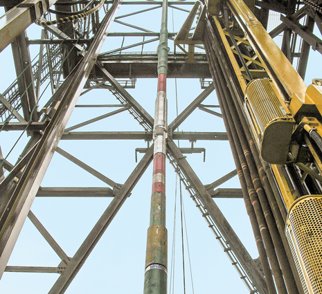
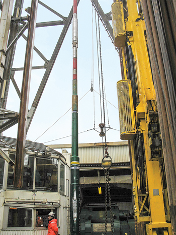
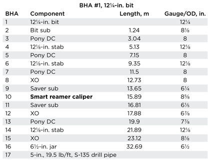
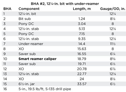
The tested smart caliper tool size had an 85/8-in. OD (with 4½-in. IF connections) and the smallest OD component in the 12¼-in. BHA. The BHA components are shown in Fig. 1, and Tables 2 and 3. If it were proven that the smaller tool could take measurements in a larger hole, this would add confidence to the overall ability of the smart caliper to function in larger hole sizes. As with previous tests, this would help provide operators with a fit-for-purpose solution that would be an improvement on existing acoustic calipers, both in measurement range and standalone, flexible BHA placement. The operator project manager was present at the tests, providing operational input and witnessing the operation.
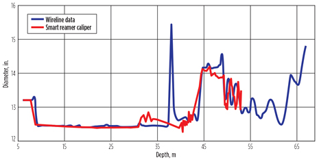
Multiple runs were performed in 12¼-in., 13-in. and 14-in. hole diameters. Drilling comprised a Smith Gemini series 12¼-in. tricone bit with Rhino Reamer, and 121/8-in. BHA stabilizers, with 65/8-in. REG connections using fresh water. The formation is a low-lying Muscovite with quartz inter-bedded graphite, granite, brittle shale and quartz, with typical strong-to-very-strong characteristics and uniaxial compressive strengths ranging from 50 to 250 MPa. TEST PROCEDUREThe smart caliper tool was surface-programmed to measure wellbore diameter and take wellbore measurements upon rotation, only. This is a user-defined parameter; rotation is not necessary for measurements and can be based on other parameters. Additionally, in this test scenario, it was useful to mark the time and number of rotations, which provided clear reference points for measurements to start and stop. The flexibility of the modular system is such that measurements can be taken independently or simultaneously. For example, in the tests, the calibration measurements were recorded independently of the caliper, but were available for processing on demand. It should be noted that the measurement of vibration also occurred independently of wellbore measurement. Similarly, reamer cutter block positions were recorded, to be compared with wellbore measurements. In this way, data from the wellbore measurements could be processed and compared with calibration, block positions, vibration, etc., or as required by the drilling application, to provide a comprehensive set of wellbore measurements and verify under-reaming. SMART REAMER CALIPER DATAThe smart reamer caliper data were recorded successfully in tool memory and downloaded at the rig floor after each run in the riser, casing and open hole, prior to under-reaming and running in the under-reamed hole. These runs were witnessed by one of the project sponsor representatives. A wireline, multi-arm caliper tool was then run to check the open hole under-reamed size from 12¼ in. to 14 in. Subsequently, the data were depth-matched (additional measurements include vibration, azimuth, inclination, temperature, pressure, RPM, WOB and torque) to form logs of wellbore diameters and wellbore profiles of Well C1, with the comparison of wireline caliper data, Fig. 2.
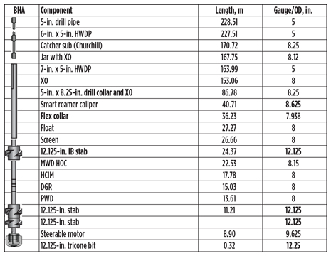
This comparison shows reasonably good matches with wireline caliper data. At 38 m, there was a noticeable measurement discrepancy at the casing shoe, because the tool was not rotated across the shoe, and the tool was programmed, prior to running in-hole, to take measurements upon rotation. In the under-reamed hole, the measurements showed good matches, except for some measured depth switches, due to wireline and drillpipe depth calculation differences. It should be noted that third-party wireline measurements were taken in an axial direction only, with six-point measurements within the wellbore, i.e. every 60°. In contrast, the smart caliper’s survey recording measurements are taken at a rate of 1,500/s. Consequently, the tool had 120 readings (or 20 times the resolution compared to the six wireline points per depth). Therefore, the smart caliper had much higher volumes of data that are available for later processing and detailed analysis by Smart Reamer Drilling Systems Ltd, or by the operator. The resolution per survey—(per 1° or fraction thereof) and according to the depth (per every 1 cm, 10 cm or 100 cm, etc.) of the Smart Caliper—can be user-defined, and increased or decreased to suit the drilling application. DRILLING TEST AT WELL 4The smart caliper tool was subject to another drilling test in the UK, with the BHA shown in component length (meters) and gauge (inches), Table 4. A single run was made to the section’s TD of approximately 800 m, and measurements performed in slide and rotary mode with hole diameters, varying in sizes of 11 in., 12¼ in., 13 in. and 13½ in. Drilling consisted of a 12¼-in. tricone bit and 121/8-in. BHA stabilizers, with a flex collar and 65/8-in. REG connections crossed over to the smart caliper tool. The drilling fluid was an environmentally-friendly, water-based mud. The formations were chalk, sand and Oxford clay, with inter-bedded shale and quartz, with typical soft-to-medium hardness on the scale and low uniaxial compressive strengths. Because the tool was placed directly above the flex collar, it was subjected to the highest bending moments and stress in the BHA. Despite this, the tool survived the 59 hr of bottom directional drilling, without any failure.
CONCLUSIONThe smart caliper tool has successfully passed the qualification tests. The characteristics of the tool system can be summarized as follows:
ACKNOWLEDGEMENTS The authors wish to thank Saudi Aramco for its permission to publish this paper and for its financial support, with additional thanks to Technology Strategy Board UK and Perenco UK for their financial and technical support. |
|||||||||||||||||||||||||||||||||||||||||||||||||||||||||||||||||
- Applying ultra-deep LWD resistivity technology successfully in a SAGD operation (May 2019)
- Adoption of wireless intelligent completions advances (May 2019)
- Majors double down as takeaway crunch eases (April 2019)
- What’s new in well logging and formation evaluation (April 2019)
- Qualification of a 20,000-psi subsea BOP: A collaborative approach (February 2019)
- ConocoPhillips’ Greg Leveille sees rapid trajectory of technical advancement continuing (February 2019)

